Single-Wheel Robot
As a summer project, I built a robot from scratch. I modeled and 3D-printed the parts, built the power electronics, and programmed it. The design is modular, allowing for two different modes of operation.
- When
- 2025
- Status
- Completed
- Role
- Solo project: design, fabrication, electronics, control & software
Overview
If I hadn’t decided to go into quantum photonics, there’s a good chance I’d have done robotics instead. There’s something immensely satisfying about building something from scratch and having complete ownership of it, and then watching it do something really cool!
The idea for this started a long time ago. Several years ago, I wanted to build a robot that looked like a single wheel but could drive around. It seemed like a challenging project, but the result would be worth it. This summer, I decided I was going to build it.
Design
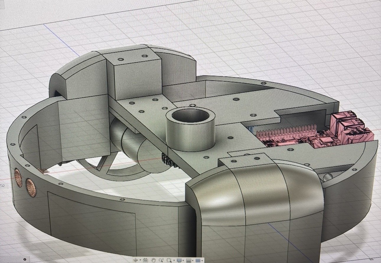
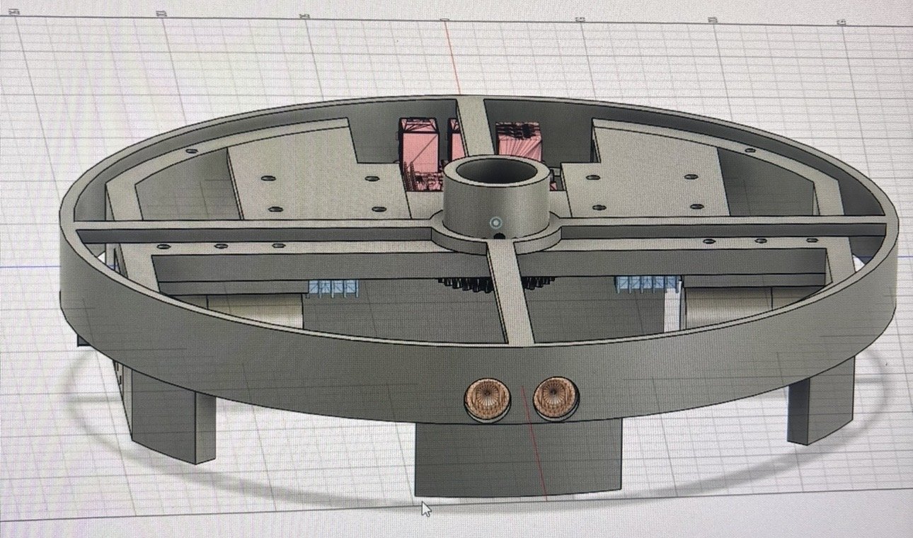
I designed every part in Fusion 360 from scratch. I wanted an initial version that was a little simpler, so I designed a chassis that was modular and could serve as a roomba-style robot.
Electronics
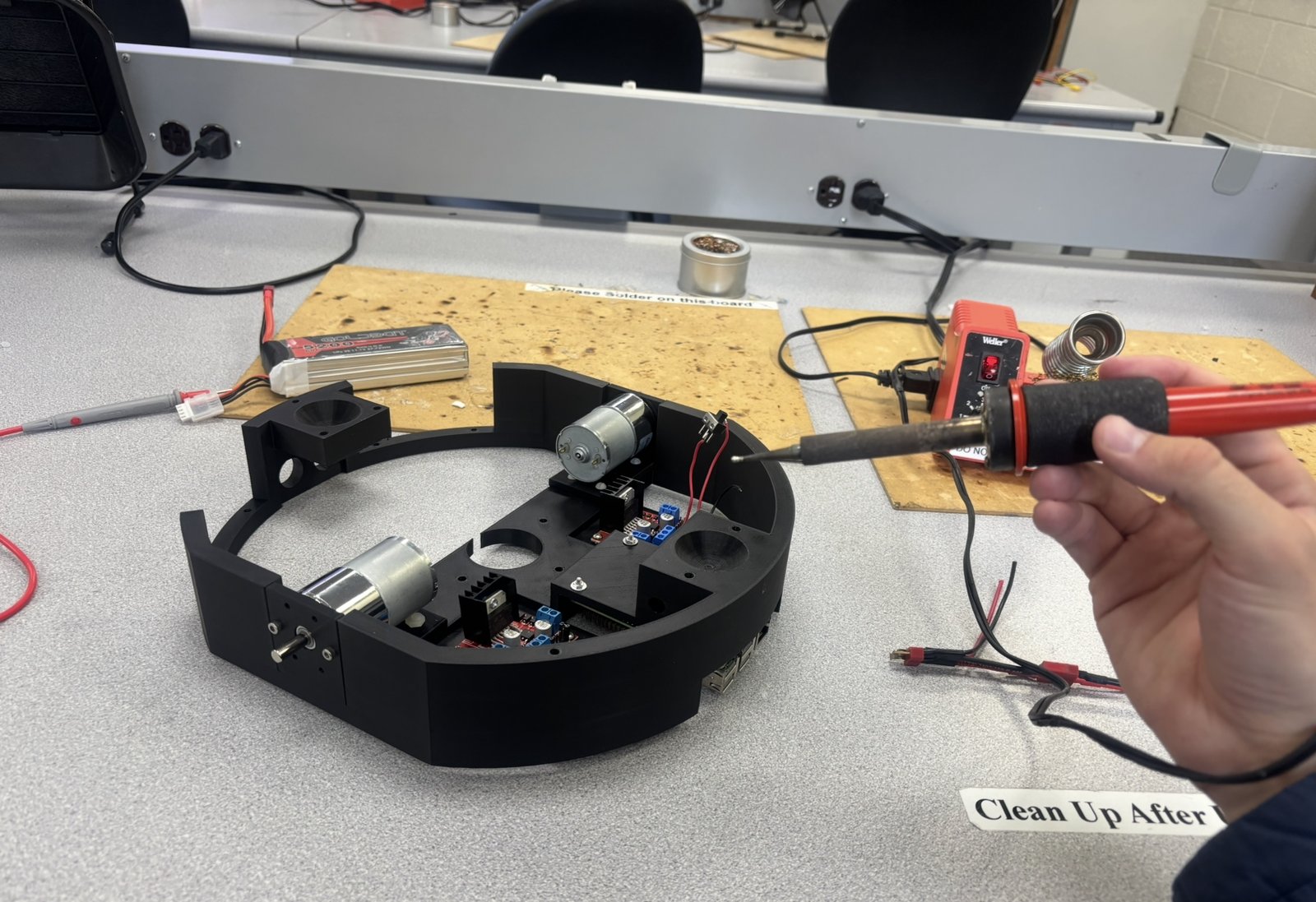
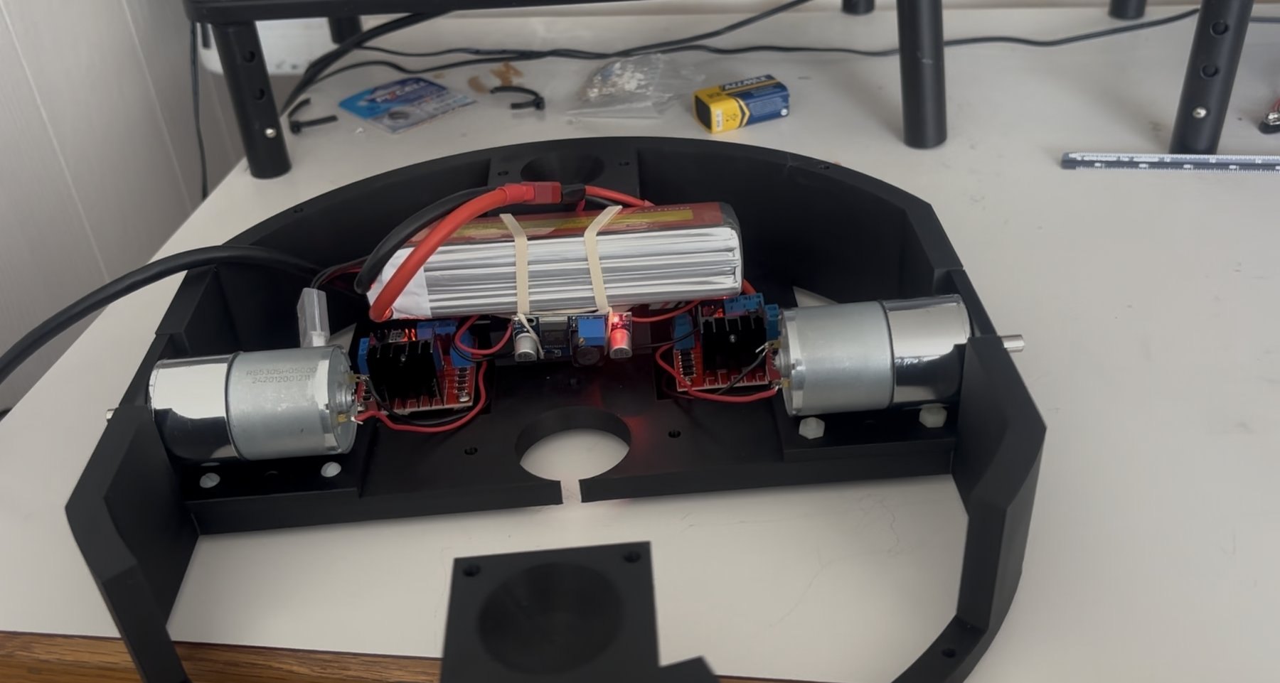
The electronics were the part I felt more confident about. Using a LiPo battery, a buck converter, and a couple of H-bridges, I created both the 12 V rail needed for the motors and the 5 V logic rail for the Raspberry Pi. The wiring wasn’t too difficult either, and when possible, I tried to solder things in place (as opposed to breadboard wiring) to reduce complexity.
First version: roomba mode
The first version worked great! It could drive around using the two motors directly attached to wheels.
Final version: the wheel
Once the roomba-style mode worked, I started adapting the design. Instead of connecting the motor shafts directly to wheels, they attached to gears that drove inner ridges on larger wheels that fit around the entire chassis. Using the same two drive motors, that allowed for independent control of two halves of a large wheel. The central chassis would then rest inside, free to spin up and down along the interior of the wheel for acceleration.
Lessons Learned
This was an awesome project! The only regret I have is that the semester started and some research deadlines came up, so I wasn’t able to work on the active control system that I wanted to make for this. I think integrating a gyroscope would have let me smooth out the acceleration and driving significantly. I still have the working robot, so that will likely be a future project when I have time again.