Laser Tag System
As part of BYU's electrical engineering junior core, I built a working laser tag system from the ground up, including the optical transmitter and receiver board.
- When
- Jan – Apr 2026
- Status
- Completed
- Role
- Optical transmitter & receiver board design
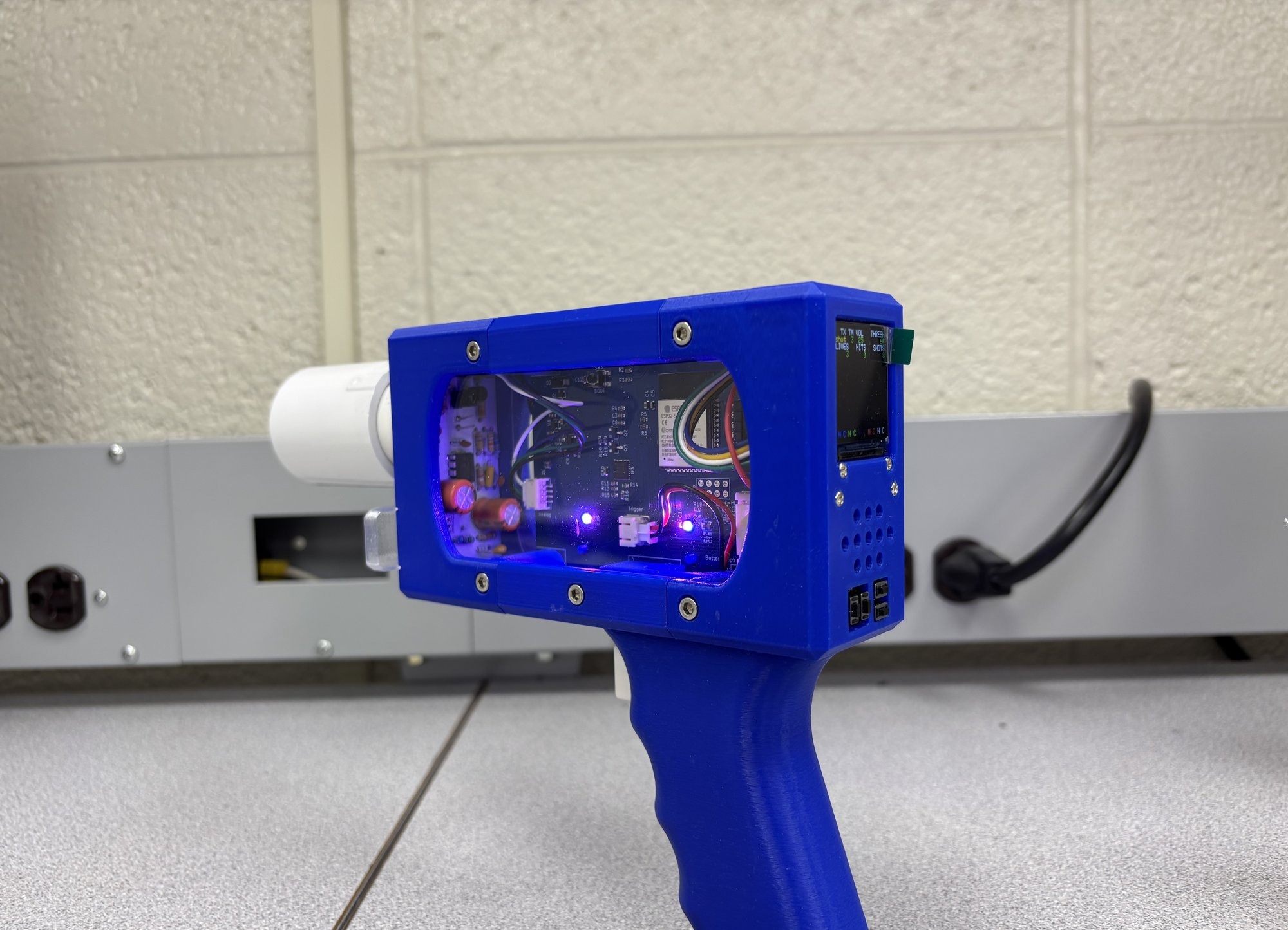
Overview
This project is a little bit different, because unlike most of the other projects I chose to highlight here, I did this one as part of a class at BYU. I mostly tried to avoid including class projects on this website, but a couple of projects in particular were too cool to ignore. This was the big junior core project at BYU, where all electrical and computer engineers have to build their own laser tag unit.
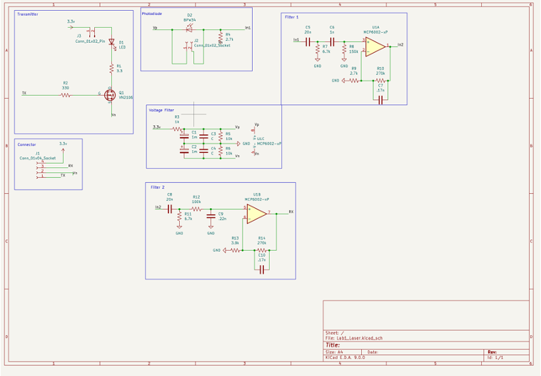
Optical front end
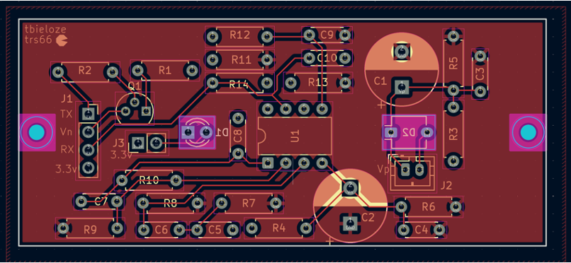
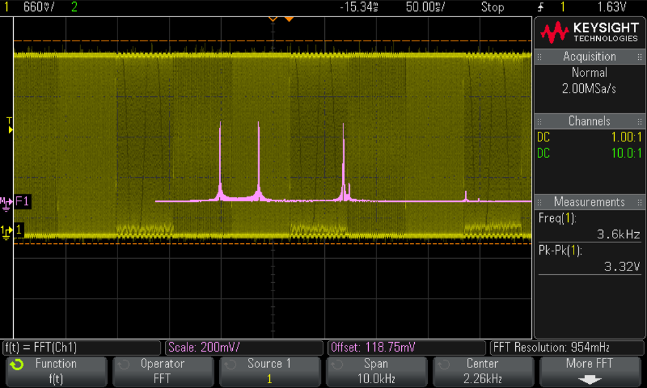
This project was done in a team of two, and I was able to team with a good friend of mine. The first part of the project was to design an optical transceiver board with the highest signal to noise ratio possible. We managed to scrape by in the top 10% of the class, so we were very happy with our design and build.
- Transmitter: An LED with PWM control to transmit on different channels, representing different teams.
- Receiver: A photodiode picks up incident light and amplifies the signal. One of the hardest challenges was isolating LED noise on the power supply from this amplifier.
- Supply filtering: The filter on the op amp supply had to be good enough that we wouldn’t rail anytime the LED was fired.
The Unit
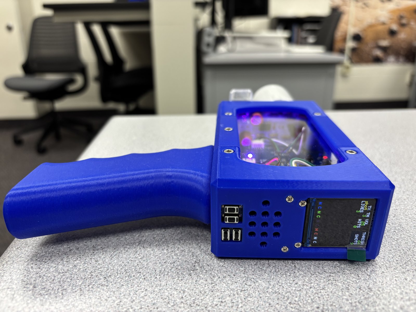
The second part of the project was working on the laser unit, including embedded programming and finite impulse response filters. We also had to code all of the game logic to interface with other units made by other teams.
Results
The main reason I enjoyed this project was that it was an opportunity to work on an embedded system and bring it together into a final project. And I think it was just super cool too! If I learned anything, it’s how I would design PCBs, 3D-printed cases and power management to build an actual product that I would sell to people. And, of course, I had some practice playing laser tag when it was all done haha.