Embedded Rust on the Raspberry Pi Pico
I worked on bringing up embedded Rust on the RP2040 microcontroller during a summer internship at Harsch Systems. There was no official SDK support, so I worked from the C SDK as a reference, which was very helpful.
- When
- 2021
- Status
- Completed
- Role
- Engineering Intern, Harsch Systems
Overview
This was my last project at Harsch Systems before I left for college, and it was probably the most difficult as well. The Raspberry Pi Foundation’s SDK for the RP2040 was written in C, but my boss wanted to be able to run Rust. This meant bringing up the embedded Rust stack directly, since at the time the RP2040 was new and unsupported (now, Rust is supported on the RP2040). I used the C SDK as a reference.
The embedded Rust stack
Trying to get Embedded Rust working on the RP2040 was incredibly difficult, and I only managed to implement a few peripherals before I finished. The Embedded Rust crate stack splits the job of talking to hardware across several crates, from low-level register access up to friendly hardware abstractions.
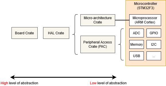 The embedded Rust stack, from high abstraction (left) to the hardware (right). The example microcontroller shown is an STM32F3, but the same structure applies to the RP2040. Figure: The Embedded Rust Book.
Register level control
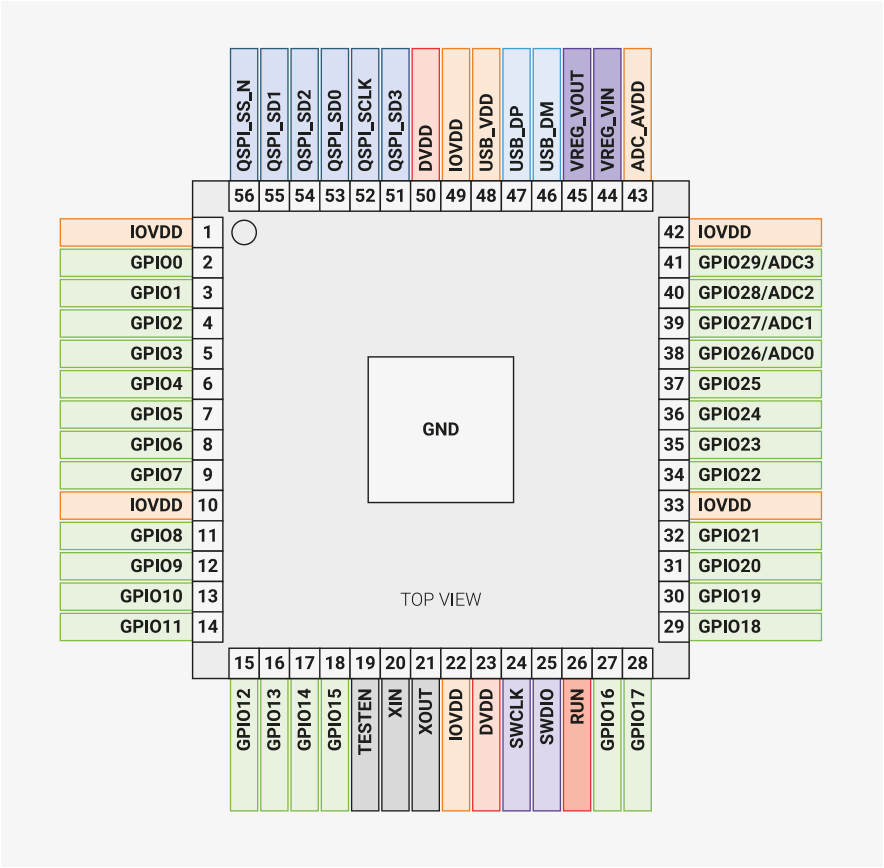
I wrote test programs for GPIO pins, the ADC, and PWM control, configuring each peripheral register by register directly via the peripheral access crate. This involved taking it out of reset, selecting pin functions, and setting up clocks, counters and duty cycles.
As an example of the code I had to write, here is the PWM setup, which brings the peripheral out of reset and configures channel 0 for a 50% duty cycle (note that I referred frequently to the official C SDK to understand the correct ordering here):
// Take the PWM block out of reset, and wait for it
p.RESETS.reset.modify(|_, w| w.pwm().clear_bit());
while p.RESETS.reset_done.read().pwm().bit_is_clear() {}

pwm.ch0_div.write(|w| unsafe { w.int().bits(0x01u8) });           // Clock divider = 1
pwm.ch0_top.write(|w| unsafe { w.ch0_top().bits(0xffffu16) });    // Counter wraps at max
pwm.ch0_cc.write(|w| unsafe { w.a().bits(0x7fffu16) });           // 50% duty cycle
pwm.ch0_csr.write(|w| w.en().set_bit());                          // Enable the channel

io.gpio[0].gpio_ctrl.write_with_zero(|w| w.funcsel().pwm_a_0());  // Route PWM to GPIO 0
This project took up only a short part of my time at Harsch Systems. In the end, I left my boss with some working examples that had been tested on an RP2040 and documentation with a guide on how to proceed.